ASMBL
Additive Subtractive Manufacturing By Layer
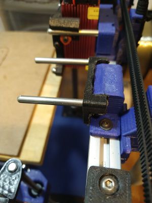
The ASMBL tool is a brushless DC motor driven spindle, controlled through a RC electronic speed controller. This is driven by the Duex5 board on a PWM pin established in the config.g and Fusion 360 post processor. The tool is attached to the Jubilee via a modified toolpost. A a 20mm vacuum line and vacuum is attached to the ASMBL for chip removal.
The Andy Everitt github for original ASMBL documentation
https://github.com/AndyEveritt/ASMBL
ESC Configuration
Update in progress
Fusion 360 Post Processor
Update in progress
Fusion 360 post processor
https://drive.google.com/file/d/1gr_61fRjwU8bOqlmvmMZSqkLpUUynF5l/view?usp=sharing
Tool Post
Milling/Engraving Workflow
The origin must be correctly placed on the top of the stock to mill/engrave prior to operation. This can be easily accomplished by jogging the tool to the desired location, raising the z height such that a piece of paper just barely gets caught under the milling bit, and then noting the x, y, and z offsets. These can then be placed into the current workspace offset with G10 L2 P1 X_offset Y_offset Z_offset. Once this has been accomplished a gcode cam path can be uploaded and started.
Tips
- Make sure you are using a PWM compatible pin with the ESC controller
- 4S motors and ESCs can use 12V PSU, 6S motors and ESCs can use a 24V PSU
- Make sure to "tie" the negative leads of both PSUs (if using multiple, like a 12V PSU for the ESC and a 24V for the printer) together and to ground in order to make sure that the signals are referenced to the same ground level
- ESCs using BLHeli firmware are known to work

