Difference between revisions of "Assembly Instructions"
Poofjunior (talk | contribs) |
|||
| Line 130: | Line 130: | ||
=== Klipper === | === Klipper === | ||
| − | * No "official path" exists for a Klipper Implementation of Jubilee, but @ImpC's [https://github.com/SteveJWallace/JubileeKlipper JubileeKlippper Repository] | + | * No "official path" exists for a Klipper Implementation of Jubilee, but there are 3 main options that you can adapt to your own motherboard and tool setup |
| + | |||
| + | * @ImpC's [https://github.com/SteveJWallace/JubileeKlipper JubileeKlippper Repository] | ||
| + | * @Xon's [https://github.com/Xonman/JubileeKlipper JubileeKlippper Repository] | ||
| + | * @TypQxQ's [https://github.com/TypQxQ/Klipper_ToolChanger Klipper_ToolChanger Repository] | ||
==First Power-Up== | ==First Power-Up== | ||
Revision as of 11:13, 27 August 2022

Building Jubilee can be broken down into the following high-level stages:
- Building the frame with tool-changer mechanism
- Connecting the electronics
- Tuning the build for its target application
- Building and connecting the tools
The instructions for the frame are detailed below.
For assembly instructions and wiring diagrams related to tools, see the page for that particular tool from the Tools page.
Questions about the assembly? Check out the FAQs, or reach out on Discord.
Hardware
For the mechanical assembly, all subassemblies are detailed with step-by-step visual instructions.
Pre-requisite Knowledge
- Working with Heat-Set Inserts via the Plate Press Technique
- Working with Inside Corner Brackets
- How to use an Arbor Press
- Tip: print this Fastener Reference Sheet at 100% scale for an easy sanity check.
- How to crimp Molex Connectors
Frame Assembly Instructions
The instructions must be completed sequentially from Section 1 to Section 3. Instructions in the same section don’t depend on each other, so they can be done at the same time with a friend.
Part Prep
Before assembling the frame:
Heat Set Insert Installation

Inside Corner Bracket Prep
Section I

Outer Frame Assembly and Alignment

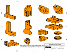
Aluminum Motor Plate Assembly
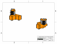
Double Pulley Corner Plate Assembly
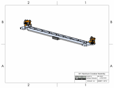
Aluminum Crossbar Assembly

Toolchanger Remote Elastic Lock Assembly
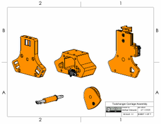
Toolchanger Carriage Assembly
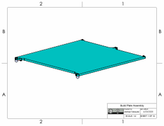
Magnetic Build Plate Assembly

Duet2 Electronics Panel Assembly
Coming Soon: Side Panel Assembly

Some instructions relate to older versions of the design. They are:
Section 2
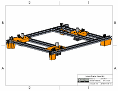
Lower Frame Assembly

CoreXY Frame Assembly
Additionally, video Links to the CoreXY assembly are provided below:
- 03 Carriage Center Installation
- 04 Y Rail Assembly
- 05 Plate Installation 1/2
- 06 Y Rail Installation
- 07 Plate Installation 2/2
- 08 Crossbar Installation
- 08 Crossbar Adjustment
- 09 Carriage Back Installation
Section 3
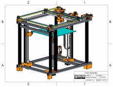
Z Axis Assembly
Electronics
Pre-Requisite Knowledge
- Crimping Wires 🠔 only if you are scratch building and not sourcing premade harnesses.
Panel Layouts
Multiple electronics architectures are supported. Refer to the Duet Layouts PDF for screw mount locations for each setup.
Wiring Diagrams
All wires needed for the frame are called out in the corresponding wiring diagrams. Important Note: XY motors and ZZZ motors have different pinouts, which means their wires will have a different color coding. This color coding is respected in the diagram, but it is easy to mix up the included cables in real life. Do keep motors and the wires they came with together as a pair. Do not mix motor cables.
Duet 2 Wiring
- Duet 2 Frame Wiring Diagram PDF
- Duet 2 Example Back Panel Layouts
Duet3 Wiring
This wiring configuration matches the existing config files for the corresponding control board.
Duet 3 Mini + 3HC Expansion Wiring
- Duet3 Mini Frame Wiring Harnesses
- Duet 3 Mini Frame Wiring Diagram
- Duet 3 Example Back Panel Layouts
Control Board Provisioning
Both the Duet2 + Duex5 Expansion board and the Duet3 Mini + 3HC configurations are fully supported.
To get a sense of the firmware requirements needed for porting Jubilee to other control boards, see the page on Adding Control Boards.
Duet 2 + Duex5
Duet 3 Mini + Duet 3HC
Duet 3 6HC + 3HC Expansion
- TODO
Duet3 6HC + Pi + 3HC Expansion
Duet3 Mini + Pi + 3HC Expansion
Klipper
- No "official path" exists for a Klipper Implementation of Jubilee, but there are 3 main options that you can adapt to your own motherboard and tool setup
- @ImpC's JubileeKlippper Repository
- @Xon's JubileeKlippper Repository
- @TypQxQ's Klipper_ToolChanger Repository
First Power-Up
Tuning
Depending on your machine's target application, you may need to do some additional tuning.
Tuning Before Your First 3D Print
Tuning Before Multicolor Drawing
Tools
For assembly instructions and wiring diagrams related to tools, see the page for that particular tool from the Tools page.