Difference between revisions of "Baby Bullet Extruder"
Poofjunior (talk | contribs) |
Poofjunior (talk | contribs) |
||
| Line 19: | Line 19: | ||
* Baby Bullet + Orbiter 1.5 + E3D Revo6 | * Baby Bullet + Orbiter 1.5 + E3D Revo6 | ||
* Baby Bullet + Orbiter 2.0 + E3D Revo6 | * Baby Bullet + Orbiter 2.0 + E3D Revo6 | ||
| + | * (Coming soon!) Baby Bullet + Orbiter 1.5 + E3D Revo Micro | ||
| + | * (Coming soon!) Baby Bullet + Orbiter 2.0 + E3D Revo Micro | ||
* Baby Bullet + Orbiter 1.5 + E3D V6 (Threaded Heatsink) | * Baby Bullet + Orbiter 1.5 + E3D V6 (Threaded Heatsink) | ||
* Baby Bullet + Orbiter 2.0 + E3D Revo6 (Threaded Heatsink) | * Baby Bullet + Orbiter 2.0 + E3D Revo6 (Threaded Heatsink) | ||
Revision as of 15:09, 8 May 2022
This is the new default extruder as of Oct 2021 (named after Caltrain.) It is a lightweight, dual-5015-fan option compatible with a variety of hotends and highly adaptable to many others.

Specs
- Modular construction enables many common extrusion options, including:
- Orbiter Extruder V1.5 and V2.0
- E3D V6, Revo V6, Phaetus Dragonfly
- E3D Groovemount or Threaded Heatsink compatible
- Aluminum Metal Tool Plate
- dual 5015 fans for extra part cooling
- one or both fans can be installed.
- 370 [grams] without wiring harness
Variants
Here is a breakdown of some of the valid combinations
- Baby Bullet + Orbiter 1.5 + E3D V6
- Baby Bullet + Orbiter 2.0 + E3D V6
- Baby Bullet + Orbiter 1.5 + E3D Revo6
- Baby Bullet + Orbiter 2.0 + E3D Revo6
- (Coming soon!) Baby Bullet + Orbiter 1.5 + E3D Revo Micro
- (Coming soon!) Baby Bullet + Orbiter 2.0 + E3D Revo Micro
- Baby Bullet + Orbiter 1.5 + E3D V6 (Threaded Heatsink)
- Baby Bullet + Orbiter 2.0 + E3D Revo6 (Threaded Heatsink)
- Baby Bullet + Orbiter 1.5 + Phaetus Dragonfly
- Baby Bullet + Orbiter 2.0 + Phaetus Dragonfly
Other versions of this tool exist in the wild too.
Parts to Buy
All parts to buy for a groovemount-style hotend are called out in this spreadsheet tab. Note that the quantity is for two extruders.
Also note that there are two heatsink types supported, but they have slightly different hardware:
Groovemount Heatsink Style

Threaded Heatsink Style


The spreadsheet above is for a groovemount style threaded heatsink. For a threaded-heatsink style hotend,
- replace the 4x M3, 20mm screws with 4x M3, 25mm screws (or 30mm for Revo Micro)
- buy 16x M3, 6mm screws instead of 14x.
- do no buy the M3 square nuts
- use a hotend with a threaded heatsink.
Assembly Tools
- 1x PTFE Tube Cutter
- 1x E3D Nozzle Spanner Wrench for hot-tightening the nozzle
- 1x Small Crescent Wrench or E3D Gripper Wrench for hot-tightening the nozzle
- 1x 3D-Printable M12 Threaded Heatsink Wrench (only if you are building a threaded heatsink style tool)
- Budget Soldering Iron for installing heat-set inserts
- Recommended: Heat-Set Insert Installation Tip. This one will work for M3 and M4 inserts.
3D Printed Parts and Settings
Print parts specific to your setup with the following print settings:
- print in the provided orientations
- PLA
- 0.4mm nozzle
- No supports
- 0.2mm layer height
- 6 perimeter layers ← this is esp important for parts with heat-set inserts
- 20% infill
- external perimeter first
- uncheck "Detect Thin Walls" if your Slicer has this settings or small gaps will not be filled.
Please check the table below for print setting exceptions.
Note that parts that peel off the bed with a small curl cannot be used. They must stick to the bed such that they remain flat.
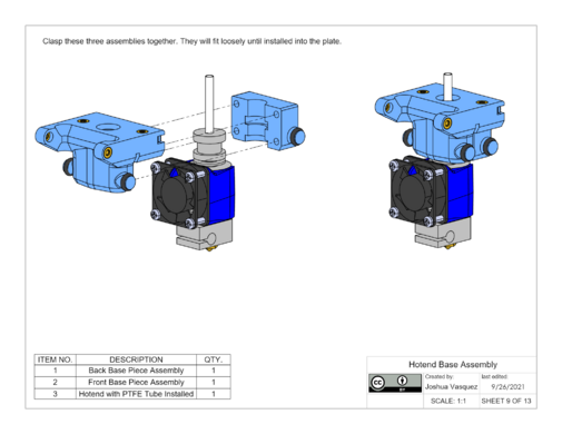
| Tool Parts | |||
|---|---|---|---|
| Quantity | Part Num | Part Source | Note |
| 1 | n/a | Top Base Piece | (Orbiter 2.0) For Threaded heatsinks. |
| 1 | n/a | Top Base Piece | (Orbiter 1.5) For Threaded heatsinks. |
| 1 | n/a | Bottom Base Piece | (Orbiter 1.5, 2.0) For Threaded heatsinks. Print with support material |
| 1 | n/a | Front Base Piece | (Orbiter 2.0) For Groovemount heatsinks. Print with support material. |
| 1 | n/a | Front Base Piece | (Orbiter 1.5) For Groovemount heatsinks. Print with support material. |
| 1 | n/a | Back Base Piece | (Orbiter 2.0) For Groovemount heatsinks. Print with support material. |
| 1 | n/a | Back Base Piece | (Orbiter 1.5) For Groovemount heatsinks. Print with support material. |
| 3 | n/a | Tool Ball Cup | |
| 1 | n/a | Left Fan Shroud | For V6 Hotend Heights. Print with support material from the build plate only. |
| 1 | n/a | Right Fan Shroud | For V6 Hotend Heights. Print with support material from the build plate only. |
| 1 | n/a | Clip Holder | (Orbiter 1.5) Print this part solid. |
| 1 | n/a | Clip Holder | (Orbiter 2.0) Print this part solid. |
| Parking Post | |||
|---|---|---|---|
| Quantity | Part Num | Part Source | Note |
| 1 | TH1840-xx | Tool Holder | |
| 1 | PPB1840-xx | Parking Post Base | |
| Printed Assembly Fixtures and Tools | |||
|---|---|---|---|
| Quantity | Part Num | Part Source | Note |
| 1 | n/a | 40mm Tool Dowel Fixture | For properly aligning parking post pins during assembly |
| 1 | n/a | M12 Threaded Heatsink Wrench | For installing a threaded heatsink |
Assembly Instructions
- Groovemount Style Tool Assembly Instructions
- Threaded-Heatsink Style Tool Assembly Instructions
- Parking Post Assembly Instructions
Wiring
- Default Wiring Diagram
- You will need to attach a 37104-A165-00E MB connector (Farnell) to the motor wires on the orbiter motor. No wire stripping required! Just insert the wires and compress the housing with a wrench.
Software Configuration
Here are the general operating conditions adapted from the Orbiter Thingiverse page:
- 681 [steps/mm] (aka: "Esteps")
- 450-500 [mA] Peak Current
- 3600 [mm/min] max extrusion speed
- 600 [mm/s^2] max extrusion acceleration
- 300 [mm/min] max extrusion jerk
- 0.03 - 0.05 [sec] Pressure Advance
- 0 [mm] nominal X offset from carriage
- 32.75 [mm] nominal Y offset from carriage
- -1.23 [mm] nominal Z offset from carriage
Duet Configuration
Creating a tool is a matter of defining a motor drive, two fans, a heater, a temperature sensor and assigning them to the tool.
Note that the order of many of these commands in the config matters. Example: you cannot refer to sensors or heaters in later lines of the config if they have not been created in previous lines of the config.
Note that the items shown in < > signs are placeholders and should be replaced with the values you actually have. (Remove the < > signs too!)
Define Extruder Steps/mm and Accel/Velocity Characteristics
Set the Extruder steps/mm ("Esteps") with:
M92 E681
Warning: if you have multiple extruders, you need to define them all at once like this:
M92 E681:830
In the above example, Extruder 0 has 681 steps/mm while Extruder 1 has 830 steps/mm. If your extruder steps/mm are all the same, you can just use one value, and it will apply it to all extruders.
Set the Tool's max speed, accel, and jerk (instantaneous change in velocity) with:
M201 E3600                ; Max Speed (mm/min)
M203 E600                 ; Max Accel (mm/s^2)
M566 E300                 ; Max Jerk (mm/min)
Warning: like before, if you have multiple extruders with different settings, you need to call them out individually with values separated by colons.
Define an Extruder Axis
The Duet ecosystem assumes that tools are connected to single extruder axis. Extruder axes are numbered starting from 0. Define an axis with:
M584 E1.0 ; Orbiter 0 on 3HC Board 1 Port 0
The first number is the Canbus board that the motor lives on. The second number is the motor index. If you have multiple extruders, you must call them all out at once separated by colons like this:
M584 E1.0:1.1
Define a Motor Drive
Each Extruder axis needs a motor assigned to it. Assign it with
M569 P<motor_drive_index> S<1 or 0> D2
<motor_drive_index> is the same value as the E value in the M584 command.
Motor direction can be set to S0 forwards (default) or S1 backwards.
If you have additional motor drives, they each get their own line.
Assign peak motor current with:
M906 E450
Warning: like before, if you have multiple extruders with different settings, you need to set them all individually separated by colons.
Define a Temperature Sensor
The Duet ecosystem assumes that each extruder has a single temperature sensor. Define this extruder's temperature sensor index.
M308 S<sensor_index> P"1.temp0" Y"thermistor" T100000 B4725 C7.060000e-8 A"<sensor_name>"
Note that the Y"thermistor" can be other types of sensors, which may have different B and C settings--or none at all! The above settings apply to a generic E3D thermistor, usually the default in a hotend setup. There is a strict syntax of name choices that can be found in the M308 documentation.
Define a Heater
The Duet ecosystem assumes that each extruder has a single heater cartridge. Define this extruder's heater index.
M950 H<heater_index> C"1.out0" T<corresponding_temperature_sensor_index>
The C"1.out0" string encodes the Canbus board address followed by the output name. The example above creates a heater and assigns it to expansion board 1's output 0.
Define a Hotend Fan
Fans are tied to PWM based outputs on a particular board. Assign a fan with:
M950 F<hotend_fan_index> C"1.out3" Q10000
Like above, the C setting assigns the fan output from a particular board on the canbus, in this case: expansion board 1's output 3.
Additional fan settings can be configured on some outputs with the M106 command. For example:
M106 P<hotend_fan_index> S255 H<heater index> T45
assigns a heater to the fan and tells the fan not to turn on unless the heater temperature exceeds 45 degrees Celsius.
Define a Part Cooling Fan
Define a corresponding part cooling fan with:
M950 F<part_fan_index> C"1.out6" Q10000              ; Define Part Cooling Fan output
M106 P<part_fan_index> C"tool0_part_cooling_fan"     ; Give it a schnazzy name
For the default fan in the BOM, the PWM frequency must be set to `Q10000` for the fan to operate at a range of output levels between 0 and 100% output.
Define a Tool
Tools are numbered starting from 0. Define the tool index, tool name, and assign it an existing motor drive, heater, and fan:
M563 P<tool_index> S"My Chocolate Extruder" D<motor_drive_index> H<heater_index> F<part_cooling_fan_index>
Nominal Offset
Define the tool's XYZ offset from the ZProbe's trigger location. These can be set to the nominal value and adjusted later when you align tools.
G10 P<tool_index> X0 Y32.75 Z-1.23
Pressure Advance
Optional: define this extruder's pressure advance value. This can be omitted (implying a value of 0), but a value of 0.1 seems to be a good starting point for this particular extruder.
M572 D<motor_drive_index> S0.03
Klipper
TODO!
Provisioning
- Setting Tool Parking Positions
- Extruder Heater Tuning
- Hot-Tightening
- With the heater tuned, you can now set the temperature and hot-tighten the nozzle.