Difference between revisions of "Mesh Bed Leveling"
Poofjunior (talk | contribs) |
Poofjunior (talk | contribs) |
||
| Line 51: | Line 51: | ||
| − | <gallery mode="packed" heights= | + | <gallery mode="packed" heights=325px> |
Image:Mesh results desktop.png|Mesh leveling results with the machine on an uneven desktop. Image Credit: @SJADO on Discord | Image:Mesh results desktop.png|Mesh leveling results with the machine on an uneven desktop. Image Credit: @SJADO on Discord | ||
Image:Mesh results floor.png|Mesh leveling results (same machine) on a hardwood floor. Image Credit: @SJADO on Discord | Image:Mesh results floor.png|Mesh leveling results (same machine) on a hardwood floor. Image Credit: @SJADO on Discord | ||
Revision as of 12:49, 28 April 2021
Most beds aren’t perfectly flat, but software measurement and compensation can account for an imperfect bed with Mesh Bed Leveling. This process collects a series of height points along a grid pattern overlayed on your bed and then saves a heightmap of the collected points. When the machine is operating, it applies a linear interpolation between heights such that XY movement also causes some small corrective movement in Z.
ZProbe Offset Assumption
In a single-extruder setup, mesh bed compensation is usually defined where the ZProbe has some XY offset from the extruder tip. Since Jubilee can change tools, we will instead collect the height map assuming a “virtual tool” that is directly on top of the ZProbe. In other words, we assume no offset during the point collection process. When we calculate tool offsets per-tool later, we will measure the offset from the virtual tool (aka: the ZProbe) and apply them there.
Instructions
Ensure that all tools are put away and that all axes are homed. Then unapply any existing Mesh offset with
M561
From here, define the grid dimensions and number of points with
M557 X10:290 Y10:290 P6
The above command tells the machine to probe 36 pts (6 x 6) within the square formed by corner coordinates (10, 10) and (290, 290). We do not recommend increasing the square size. However, you can increase the number of points per axis if you like. The process will simply take longer with marginal gains.
Next execute the probing with
G29
When the process completes, a window with a heightmap should pop up that looks something like this:

After inspecting and closing the window, the settings will be saved to the SD card, but you must still tell the machine to apply the mesh bed compensation. The best place to do this is in the homez.g file. At the very beginning of the file, add
M561
and at the very end of the file, add
G29 S1
Doing so cancels existing offsets before running the 3-point bed leveling process and then applies them as soon as the 3-point leveling process is finished.
Interpreting the Results
After computing the mesh above, it's worth asking: how do I know if this is this good enough? Anecdotally, if your mesh results are neither red nor blue, your setup is more than sufficient for printing and likely cannot be improved. For more details and troubleshooting improvements, read on.
MIC6 Specs
Bed plates are cut from cast tool plate aluminum, the most common of which is MIC6. Cast tool plate is a stress relieved material such that, in principle, when heated, it expands uniformly. In practice this may not be entirely the case, which is why creating a mesh when the plate is at printing temperature may capture a more accurate representation of any deformations in the plate.
MIC6 is surface machined by a large fly cutting tool at the factory, making it very flat, within 0.381mm across the entire span of the raw sheet stock. If your mesh results are within this value, your setup is with the flatness specifications of the plate.
Twist in the XY Frame

In cases where your mesh deviates beyond the MIC6 spec in a twisting fashion like the image on the right, it's possible that this flatness deviation is not due to the plate but due to upper frame of the machine itself. Ideally, the XY motion system moves the carriage in a perfect plane. In practice, some slight skew in the frame introduced during the assembly process can cause this plane to be twisted. To check for skew, measure the vertical distance between upper and lower frames at all four corners of the machine. If they differ more than 0.1mm, unscrew these corners such that all heights are equal. Note: the heights do not need to be the nominal dimension from the CAD model; they simply all need to be equal to each other within a tight tolerance.
Should I worry about Frame Twist?
Even if your mesh results are as twisted as those shown on the right and the twist is coming from imperfections in the frame, not the plate, it's still possible to get excellent printing results. Here's why. Remember that this plane is a height correction applied in Z as the printer travels over the surface in XY. This correction is compensating for imperfections on both the plate and the frame. The result is that the distance between nozzle and bed remain constant as the nozzle makes XY travel movements over the bed. As a result, the bottom surface of your 3D print will always be as flat as your bed plate, and no flatter.
When to Re-Mesh
While this operation should normally be a one-time thing upon commissioning the machine, some circumstances may necessitate re-running mesh bed leveling. They include:
Moving the Printer
Because the printer feet cannot be adjusted, the weight of the printer deforms the printer frame such that the four feet contact the table. The result is that any unevenness in the table surface at the four points will propagate as XY twist in the frame. While, this issue is correctable and does not propagate as errors in the parts (see the section above on twist in the XY frame), the result is that you may need to rerun mesh bed leveling each time you move the printer to a different surface.
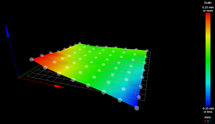
Mesh leveling results with the machine on an uneven desktop. Image Credit: @SJADO on Discord
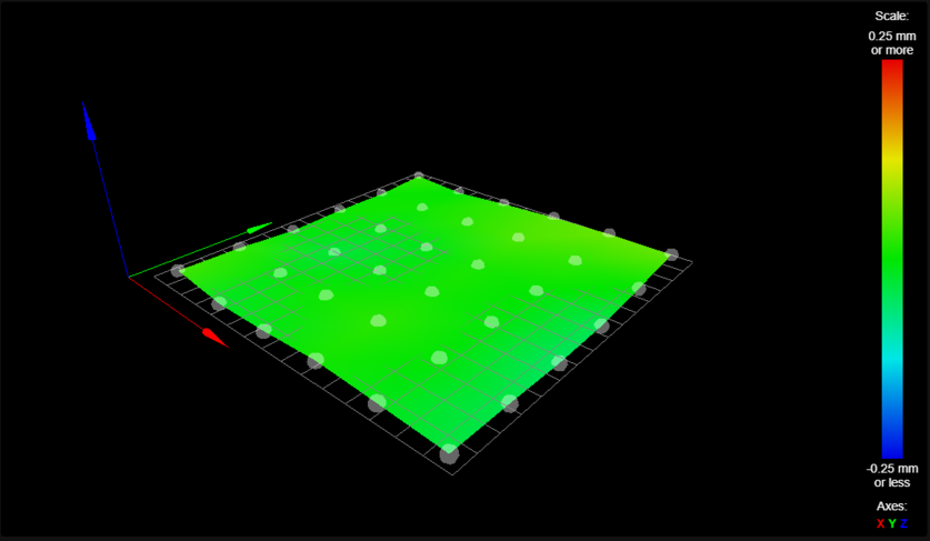
Mesh leveling results (same machine) on a hardwood floor. Image Credit: @SJADO on Discord


Frame Servicing and Reassambly
Dismantling and reassembling any part of the frame may introduce slight XY twists. Again, while this issue is correctable and does not propagate as errors in the parts, it will require a new mesh.